Product Description
The RM200/RM100 series (hereinafter referred to as M200, M100) motor protector is the latest release of Renle Technology, an intelligent motor management system based on microprocessor technology. Through the M200/M100 motor control device MCU and advanced fieldbus communication technology, M200 and M100 provide a set of professional intelligent management solutions for low-voltage motors that integrate control, protection and monitoring. They are process control systems for motor intelligence. Ideal choice for management.
M200 is divided into M200-M and M200-P M100
according to the communication protocol. As a simplified version of M200, only
M100-M is available.
Features:
Comprehensive motor control, protection and monitoring
The M200/M100 motor protector monitors,
controls and protects the motor operation through on-site motor control and
protection devices, and combines the communication function of the device with
the upper computer monitoring system to realize the intelligent monitoring,
control and protection of the motor.
Perfect motor protection
Perfect motor protection is to collect and
track the detailed information of various operating conditions during the
operation of the motor, and realize timely and accurate protection through the
setting of fault alarm, protection action (protection trip) and action delay
time to ensure production safety. At the same time, through communication, the
detailed information of the motor's operating status can be monitored in real
time on the host computer, and management information can be provided through
computer data processing. Before the equipment may cause a major failure, the
over-limit alarm can promptly remind the management staff to deal with it,
avoiding unnecessary downtime and affecting normal production, and ensuring the
effectiveness of equipment operation to the greatest extent.
When the motor operating parameters reach the preset alarm value, the protection device only alarms and does not trigger the trip; but when the limit value reaches the preset trip value, the protection device enters the trip trigger delay. If the equipment returns to normal operation within the preset trip delay time, the trip execution will be canceled; and if the delay time is exceeded, the protection device will send a trip signal, drive the actuator to act, and stop the motor. While the motor control device realizes various protection functions, various protection information is also generated by the device and sent to the computer management system via the communication interface.

Features of M200/M100 Motor Protector
● Various protection functions have been built into the device, which can be configured according to actual needs, saving users the trouble of selecting models.
● Chinese and English operation panel
display.
● The required protection function can be
easily selected on the computer through the setting software, and the required
parameters can be set. It is very convenient for multiple similar settings;
● Downloading the set parameters to the
protector through the download line is fast and accurate, and it is also easy
to archive;
● The main function parameters of the
protector can also be manually modified through the panel.
● According to the characteristics of the
protection function, it can be set as alarm and delayed tripping, only alarming
without tripping or directly entering the delayed tripping protection,
● Such an early warning mechanism enables
users to take corresponding measures in advance to avoid the loss of production
caused by parking.
● By pre-setting the protection trip reset
mode, the user can choose the reset mode of the fault protection trip.
Different protection functions have different reset methods:
- Automatic reset
-Remote reset
-Local reset
● Built-in current transformer, allowing
users to flexibly expand the current transformer through simple parameter
setting.
● The built-in transformer of the protector
body is allowed to be used in the range of motor rated current 0-63A. When the
motor current is greater than 63A, use an external current transformer to
expand.
Technical index:
Electrical parameters
Main circuit rated working voltage Ue230/400V or 400/690V
● Rated insulation voltage Ui690V
● Rated current Ie0.5-63A
● Rated operating frequency 50-60 Hz
control
Circuit rated working voltage Ue230VAC
● Rated insulation voltage Ui250V
● Rated operating frequency 50-60 Hz
Protection grade IP20
● M200/M100 working power supply voltage Ue220Vac
● Operating supply voltage supply voltage
range 85-115%
● Control output relay output capacity 5A /
230V
● Programmable relay output output capacity
5A / 230V
Environmental conditions
● Storage temperature -25~+85°C
● Working temperature-5~+60°C ◆ring
● Ambient humidity 15% ~ 95%, no
condensation
Application wiring diagram
Figure 1: M100 direct start control principle diagramDescription:
1) When the motor Ie<=63A, no external CT is required; when the motor Ie>63A, an external protective CT is required. Refer to Note 1 for the wiring of the CT.
2) The zero sequence transformer TA0 needs
to be matched with M100-P; S is the auxiliary contact of the drawer handle,
which is only connected in the test position.
3) When the capacity of the contactor KM
exceeds the output capacity of the control relay (CCA, CCB) (AC15 2A/230V, DC13
2A/24), the capacity needs to be expanded through the intermediate reay.
4) DIx (DI0-DI12) are programmable input terminals, which need to be set by parameter setting software. In the figure, DI2, DI4, DI5, and DI6 are set to Star1, Stop, Loc/R, and F_CA respectively. For more information, please refer to parameter settings manual.
5) The contactor coil must be connected in
parallel with the surge suppressor matched with the contactor, see Note 5.

Note 2: DIx refers to the terminals DI0~DI12 on M100-P. To realize the control function, it needs to be pre-set through the parameter setting software. For more information, please refer to the parameter setting manual.
Note 3: DS control is optional
Note 4: The wiring of zero sequence
transformer needs to use shielded wire
Figure 2: M100 direct start (with control button box) control principle diagram
Description:
1) When the motor Ie<=63A, no external CT is required; when the motor Ie>63A, an external protective CT is required. Refer to Note 1 for the wiring of the CT.
2) The zero sequence transformer TA0 needs
to be matched with M100-P; S is the auxiliary contact of the drawer handle,
which is only connected in the test position.
3) When the capacity of the contactor KM
exceeds the output capacity of the control relay (CCA, CCB) (AC15 2A/230V, DC13
2A/24), the capacity needs to be expanded through the intermediate relay.
4) DIx (DI0-DI12) are programmable input
terminals, which need to be set by parameter setting software. In the figure,
DI2, DI4, DI5, and DI6 are set to Star1, Stop, Loc/R, and F_CA respectively.
For more information, please refer to parameter settings manual.
5) The contactor coil must be connected in
parallel with the surge suppressor matched with the contactor, see Note 5.

Note 2: DIx refers to the terminals DI0~DI12 on M100-P. To realize the control function, it needs to be pre-set through the parameter setting software. For more information, please refer to the parameter setting manual.
Note 3: DS control is optional
Note 4: The wiring of zero sequence
transformer needs to use shielded wire
Figure 3: M200-P direct start control principle diagram
Description:
1) When the motor Ie<=63A, an external CT is not required; when the motor Ie>63A, an external protective CT is required. Refer to Note 1 for the wiring of the CT.
2) The zero sequence transformer TA0 needs
to be matched with M100-P; S is the auxiliary contact of the drawer handle,
which is only connected in the test position.
3) When the capacity of the contactor KM exceeds the output capacity of the control relay (CCA, CCB) (AC15 2A/230V, DC13 2A/24)Need to expand the capacity through the intermediate relay.
4) DIx (DI0-DI12) are programmable input
terminals, which need to be set through parameter setting software. In the
figure, DI2, DI4, DI5, and DI6 are set to Star1, Stop, Loc/R, and F_CA
respectively. For more information, please refer to parameter settings manual.
5) The contactor coil must be connected in
parallel with the surge suppressor matched with the contactor, see Note 5.

Note 2: DIx refers to the terminals DI0~DI12 on the M200-P. To realize the control function, it needs to be pre-set through the parameter setting software. For details, please refer to the parameter setting manual.
Note 3: DS control is optional
Note 4: The wiring of zero sequence
transformer needs to use shielded wire
Figure 4: M200-M direct start wiring diagram (with button box next to the machine)
Description:
1) When the motor Ie<=63A, an external CT is not required; when the motor Ie>63A, an external protective CT is required. Refer to Note 1 for the wiring of the CT.
2) When the capacity of the contactor KM
exceeds the output capacity (5A/220V) of the control relay (CCA, CCB), the
capacity needs to be expanded through the intermediate relay.
3) DIx (DI0-DI8) is a programmable input
terminal, which needs to be set by parameter setting software, in the figure:
DI2-start; DI4-stop;
DI5-remote control/local; DI6-contactor
feedback; DI7-reset; DI8-emergency stop; please refer to the parameter setting
manual for details.
4) The contactor coil should be connected
in parallel with the surge suppressor matched with the contactor, see Note 5.

Note 2: DIx refers to terminals DI0~DI8 on M200-M. To realize the control function, it needs to be pre-set by parameter setting software. For more information, please refer to the parameter setting manual.
Note 3: DS control is optional
Communication connection

The M200/M100 motor control device communicates with the upper management system through the device's communication interface. M200-M and M100-M have redundant communication interfaces. M200-P can be expanded by a repeater on a bus. The tree topology can be expanded at most.Connect 125.
Product Model
Product model description:

Note: Only one of motor temperature protection and 4-20MA output function can be selected
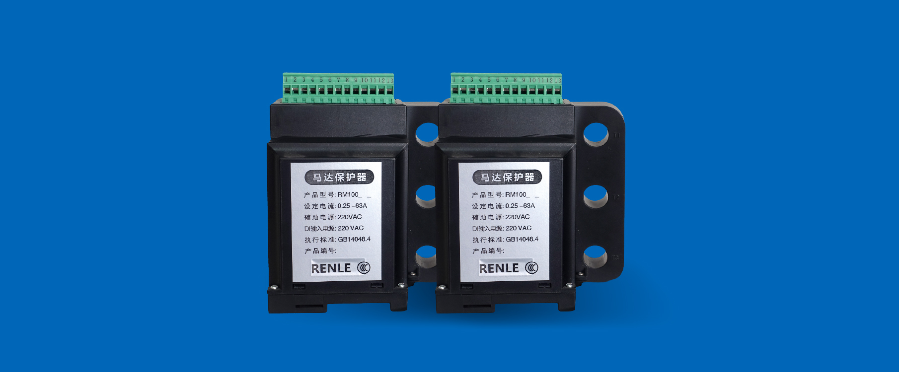
product structure:
Motor control device
motor control device includes two specifications, M100 and M200.The functions provided by M100 include basic motor control,

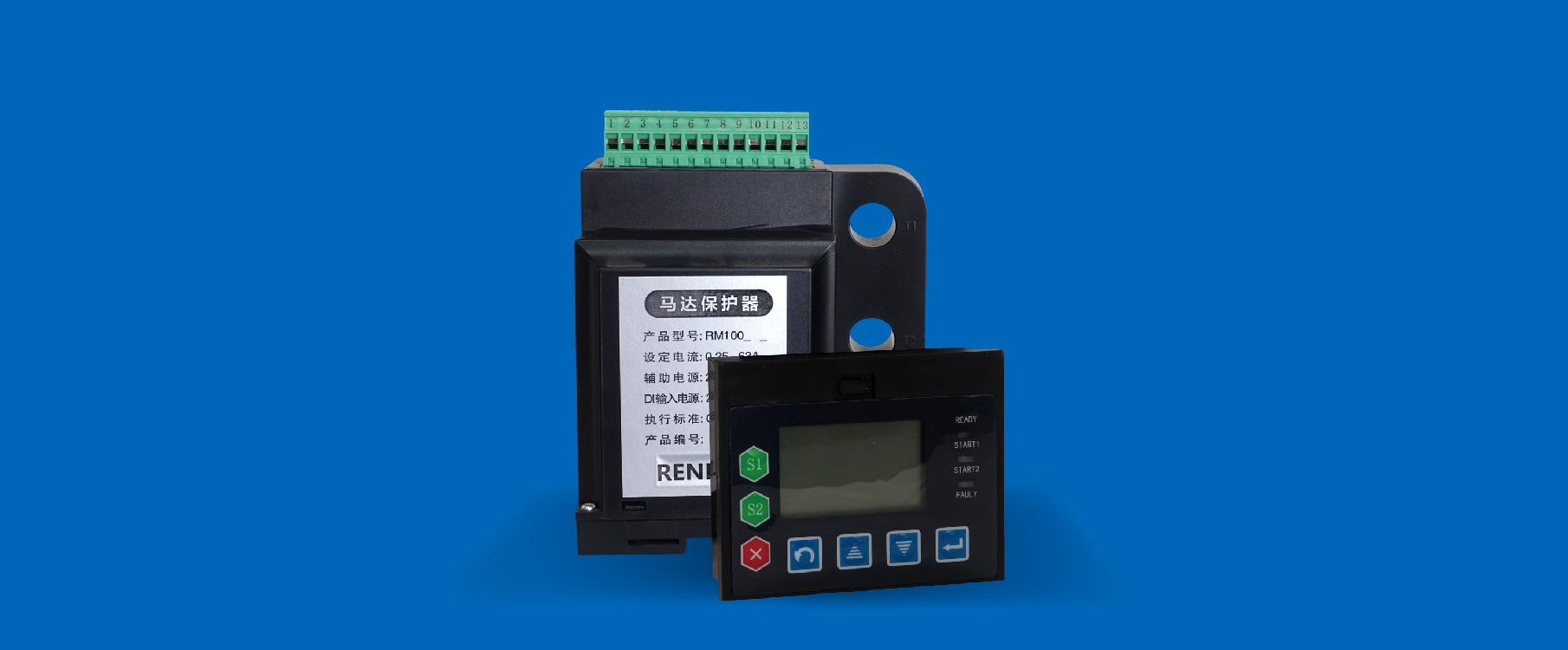
Operation panel for motor control and monitoring
M200 / M100 are equipped with an operation panel, which is used to display the operating status of the motor and control the start and stop of the motor. At the same time, it provides an entrance for the field parameter setting and programming of the M200 / M100.
The operation panel integrates the
functions of meters, indicators, buttons and fault monitoring functions, and is
connected to the M200 / M100 through the communication line.Through the
debugging interface provided by the operation panel, the M200 / M100 can be
easily set up on site and programmed online with a laptop.


The size of M200/M100 host is as follows:

Host installation method: adopt TS35 rail installation, the terminal faces upwards during installation.
The dimensions of the control panel are as follows:

The installation adopts embedded upper and lower card slots.
Mechanical Dimensions

About the following order
1. Control host:
1: M200-M-T has Modbus-RTU communication, comprehensive functions, motor temperature protection but no 4-20MA output standard.
2: M200-M-W has Modbus-RTU communication,
comprehensive functions, 4-20MA output but no motor temperature protection.
3: M200-P-T has Profibus communication,
comprehensive functions, motor temperature protection but no 4-20MA output
standard.
4: M200-P-W has Profibus communication,
comprehensive functions, 4-20MA output but no motor temperature protection.
5: M100-M has Mudbus RTU communication
function and basic functions of motor protection.
2. Display control box:
M200/M100 series universal (provided with host)
3. communication line
Connect the display control box and the host (1.2 meters provided with the host, order for more than 2 meters)
4.programming line
For computer programming, additional purchase is required
5.zero sequence transformer
For zero sequence protection, additional purchase is required
6.external transformer
Motor rated current greater than 63A requires external transformer (200A/5A, 300A/5A, 500A/5A)